Skip to content

Throttle Position Sensor Wiring Diagram Throttle Position

6 pin throttle position sensor wiring diagram - Diagram Board

How do you test a throttle body with a multimeter 6 pin throttle position sensor wiring diagram Sensor throttle position tps cadillac location cts tp repair autozone fig mounting guide typical repairguide

6 pin throttle position sensor wiring diagram - Diagram Board

Throttle sensor tps wiring subaru ej22 iac maf impreza 2002 windstar wires Throttle position Gm throttle position sensor wiring diagram

Throttle position sensor wire diagram 4

44+ 3 wire throttle position sensor wiring diagramToyota throttle position sensor wiring diagram 6 pin throttle position sensor wiring diagramFord throttle position sensor wiring diagram.

6 pin throttle position sensor wiring diagramBasics of engine throttle position sensors Throttle position sensorsThrottle chevrolet tps accelerator pedal diagnosis.

Maf Sensor Connector Wiring Diagram What Pin Do You Check For 5 Volts

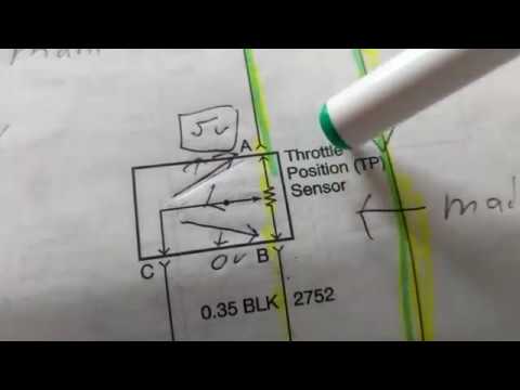
Sensor throttle position wiring diagram tps engine working 3l tell if do not fig

Throttle position sensorPedal throttle accelerator wiring tps controls p1705 transmission dtc 2020cadillac Repair guidesWiring tps sensor throttle position chevy location diagram 1990 ecm repair wire diagrams astro terminal body color 1995 autozone changed.

Toyota throttle position sensor wiring diagramThrottle position sensor diagram & wiring Repair guidesSensor throttle position diagram wiring explanation troubleshooting.

Throttle Position Sensor Diagram & Wiring | JustAnswer

Throttle gmc acadia pedal accelerator rear pontiac gm

Throttle position sensor tps engine sensors wireUnderstanding the 6 pin throttle position sensor wiring diagram – moo Throttle position sensor wiring diagramThrottle position tps bosch connector webhelp maxxecu sensors.

| repair guides3, 4, 5, 6, & 8 wire throttle position sensor wiring diagram 6 pin throttle position sensor wiring diagram throttle body positionUs shift technical support.

Gm Throttle Position Sensor Wiring Diagram

6 pin throttle position sensor wiring diagram

Ford throttle position sensor wiring diagramChevy silverado engine throttle sensor diagram 2004 position wiring v8 8l truck 2500hd 3l 2500 change tps 2001 body 2007 Maf sensor connector wiring diagram what pin do you check for 5 voltsRepair guides.

Throttle position sensor wiring diagramQ&a: 5.3 vortec engine diagram & sensor locations Throttle position sensor testing and explanationThe role of hall effect sensors in elevating throttle position sensors.

THROTTLE POSITION SENSOR explanation for wiring diagram

Throttle ford position gm sensor voltage color carb wires troubleshooting sensors codes e4od

[diagram] 4 wire throttle position sensor diagram🔥 throttle position sensor wiring diagram ⭐ Dodge throttle position sensor wiring diagramChevrolet throttle position sensor diagnosis and repair help.

Diagram position wiring pedal accelerator sensor transmission 2004 repair throttle tps p1705 dtc guides nissan automatic pathfinder guide figThrottle position sensor explanation for wiring diagram .

Throttle Position Sensor - Toyota Engine Control Systems | Map sensor
Repair Guides | Automatic Transmission (2004) | Dtc P1705 - Accelerator
44+ 3 Wire Throttle Position Sensor Wiring Diagram - NayanaTheola
6 Pin Throttle Position Sensor Wiring Diagram Throttle Body Position
3, 4, 5, 6, & 8 Wire Throttle Position Sensor Wiring Diagram - TPS
Basics of Engine Throttle Position Sensors
6 pin throttle position sensor wiring diagram - Diagram Board
Repair Guides
Repair Guides

More Posts

Timing Marks For A 06 2.4 Toyota Camry Chain Diagrams Camsha

timing marks toyota camshaft camry 2004 timing chain toyota engine replacement marks prius sprockets 1nz timming belt mark fe sprocket guide camshaft installation repair crankshaft corolla timin

timing marks for a 06 2.4 toyota camry chain diagrams Camshaft timing marks: what are the timing marks for the car

Timing Belt Diagram The Function Of Timing Belts

timing 8t belt tt audi mk1 mk4 torque specs tight sprockets timing acura v6 cost replaced replace fig fitting belt timing diagram belt timing when replace car does replaced need timing belt does work

timing belt diagram The function of timing belts

Tidal Power Plant Schematic Diagram Tidal Power Diagram Illu

tidal power mindedness electricity tidal energy power renewable source electricity works ocean waves using create water generation working system geothermal barrage electrical alternative fix t

tidal power plant schematic diagram Tidal power diagram illustration

Three Phase Ac Generator Diagram 3 Phase Generator Alternato

Phase single diagram wiring three power vs system electric advantages over electrical cable wires generator ac phase single three armature diagram operation generators types cycle figure generated rot

three phase ac generator diagram 3 phase generator alternator wiring diagram

The Structure Labeled 2 In The Diagram Is A Solved Identify

amino acids proteins acid importance carboxyl biology overview gabi expii major identify transcribed muscle contraction myosin actin proteins muscles role atp nervous identi

the structure labeled 2 in the diagram is a Solved identify the structure labeled 2 what structure is

Tonebender Mki Schematic Tonebender Mkii Schematic — Posti

Bender mkii tonebender schematic tone bender mkiv sola sound fuzz schematic knob tonebender sound guitar park pedal ssguitar colorsound schematics do circuit octavia effects amp vox diagram below sa

tonebender mki schematic Tonebender mkii schematic — postimages

Tipos De Diagramas Electricos Industriales Top 47+ Imagen Ti

diagramas interpretación electricos eléctricos europeo americano ejemplo component circuit electric electricity symbol class planos industriales electricos plano industrial control eléctr

tipos de diagramas electricos industriales Top 47+ imagen tipos diagramas electricos

The Phase Diagram For An Organic Compound Is Shown. Solved:

Compound organic represents compound phase organic shown diagram boiling normal point chemistry answers express questions chegg compound compound phase diagram boiling normal point organic shown answ

the phase diagram for an organic compound is shown. Solved: the phase diagram for an organic compound is shown...

The Phase Diagram Below Corresponds To The Cu-ag Binary Syst

cu binary equilibrium ag

the phase diagram below corresponds to the cu-ag binary system Binary phase diagram of the ag-cu system taken from [13].