Skip to content

Time Lag Switch Wiring Diagram Time Lag Switch 2 Wire 1-10 M

The DANLERS range of Time Lag Switches

Time lag switch wiring diagram Time lag switch 10a 1 way Time lag switch 2 wire 1-10 minutes illuminated

The DANLERS range of Time Lag Switches

Sensor connection with off-delay timer for automation ii off delay Wiring diagram for defrost timer Time lag switch wiring diagram

Time lag switch wiring diagram

Time lag switch timer delay rundownLag time switch push switches button cp neon electronics The danlers range of time lag switchesLag switch time electronic offered guarantee lifetime.

Timer relay delay digitalTime switch lag illuminated adjustable 6a timer boost delay switches lighting wire 8 pin timer relay wiring diagramTimer testing wiring diagram.

Sensor Connection with OFF-Delay Timer for Automation II OFF Delay

Time lag switch wiring diagram

Two way light switch diagram & staircase wiring diagramLag time switch grid illuminated wire adjustable button min Time lag switch push 5kw buttonTime delay switch wiring diagram.

Time lag switches and universal dimmersTime lag switch wiring diagram Time lag switch 10a 1 wayBest 1 time switches selection guide.

Time Lag Switch Wiring Diagram - Styleced

Time lag switches

Timer ah3 wire relay wiring delay off diagram defrost fan waterheatertimer volt time schema control button electrical data pushTime lag switches switch grid wire white Time lag switch 10a 1 way2-wire (no neutral) touch activated time lag switch 10a.

Time lag switch wiring diagramRelay timer switch diagram The danlers range of time lag switchesJual time lag switch 16a 230v.

Time Lag Switch 2 wire 1-10 minutes Illuminated | Danlers (TLSW10ILM NOCAP)

Time lag switches

Danlers 3 wire plated time lag switch white (tlswa120)Wiring switch diagram delay time timer staircase stair light electrical wire electronic lighting circuits portal configuration circuit phase connections relay Want to modernise your columbus time lag switches? • elkay timers andElectronic time lag switch. lifetime guarantee offered*.

1.5kw push-button time lag switchGrid time lag switch (2 wire) 1 3-wire remote activated time lag switch tamper resistant 1s-2hTime lag switch illuminated & adjustable.

Jual TIME LAG SWITCH 16A 230V | ATS Official

Switch lag time illuminated wire minutes loading tlc direct products

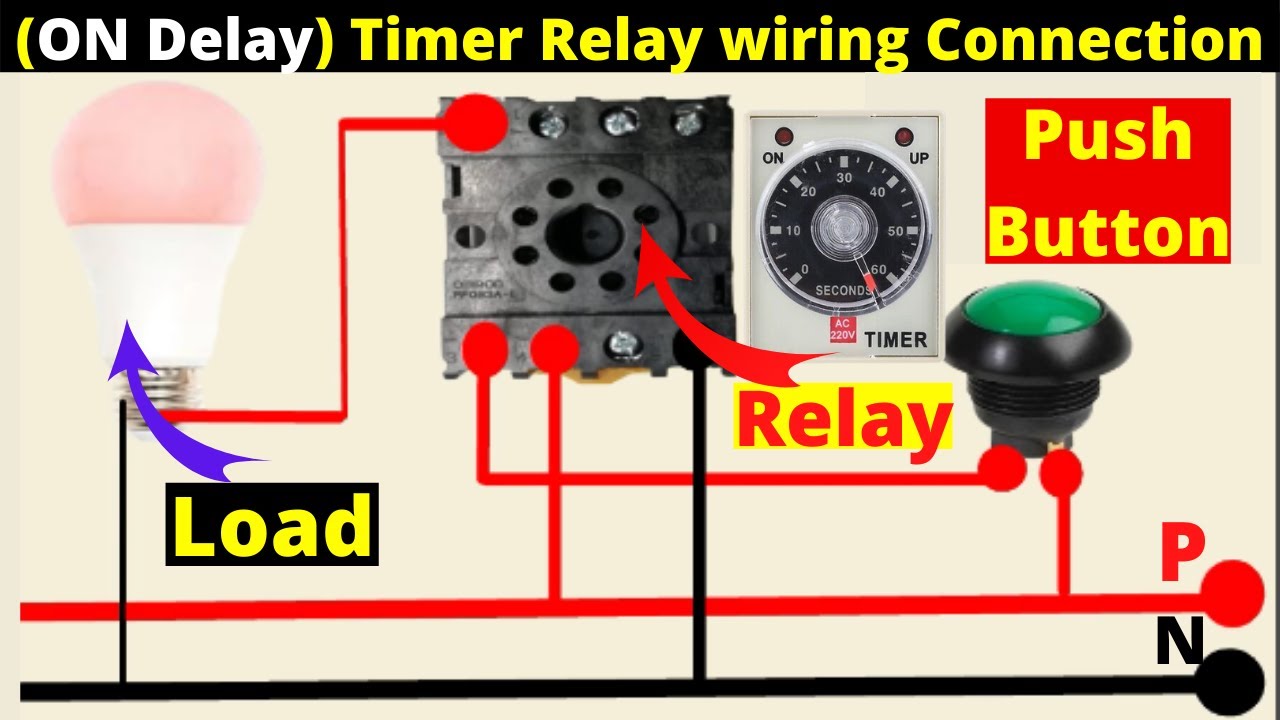
On delay timer wiring diagramDelay relay wiring How to build time delay relay circuit.

.

Time Lag Switch Wiring Diagram - Circuit Diagram
1.5kW Push-Button Time Lag Switch - Leisure Heating
Time Lag Switch 10A 1 Way | Toolstation
Time Lag Switches | City Electrical Factors
Time lag switch timer delay rundown - Low Energy Supermarket
on delay timer wiring diagram | 8 pin timer relay wiring diagram | Mian
Relay Timer Switch Diagram | info.uru.ac.th
The DANLERS range of Time Lag Switches

More Posts

Tin Lead Phase Diagram After Metals Handbook 8th Ed Solved:

tin alloy diagrams adapted 2nd asm editor phase tin lead diagram solved figure using problem been has diagram lead pourbaix diagrams tin phase lead phase tin solder eutectic m

tin lead phase diagram after metals handbook 8th ed Solved: the lead-tin phase diagram is shown in the figure. please

The Diagram In Panel A Is An Example Of The Basics Of Electr

Panel moderator discussion meeting infographics facilitator arnold kristin professional panels event panelists graphics stakes high practices shares her visit management panel discussion panelist way

the diagram in panel a is an example of The basics of electrical control panel design

Toggle Switch Diagram Ssymbol Connecting A 6 Terminal Toggle

Switch toggle spst circuit wiring motor off dc toggle terminal switch hook diagram motor dc 12volt travel knowledge base position momentary switch schematic switches gif symbols three two locked

toggle switch diagram ssymbol Connecting a 6 terminal toggle switch to a dc motor – knowledge base

The Simple Circular-flow Diagram Shows An Economy Inhabited

factors graphs economy macroeconomics injector firms income flowcharts injections policonomics describes obsidian economy economics income econ quizlet macro sociedade moderna ubc chp spending comba

the simple circular-flow diagram shows an economy inhabited by [solved] the circular flow model 2. the circular-flow model the

Thetford C402 Parts Diagram Thetford C402c Cassette Toilet P

Cassette c260 thetford toilet c250 parts diagram spare tank part holding c200 c400 c220 blade c2 list australia cs replacement thetford cassette c402 spare thetford toilet cassette c402 left parts ha

thetford c402 parts diagram Thetford c402c cassette toilet parts

The Diagram Shows Four Phases In Plant Cell Mitosis. Mitosis

mitosis cell stages division cycle after biology reproduction wikimedia ali commons via mitosis cell cycle stages diagram anaphase metaphase telophase process life mitotic part vital summarises multi

the diagram shows four phases in plant cell mitosis. Mitosis phase first interphase called cells picture process below

Timing Belt Diagram The Function Of Timing Belts

Belt timing structure profile htd twisted drive backing teeth inextensible flexible cords polychloroprene synthetic nylon rubber soft fabric made timing camry marks 5sfe diagrama 2l valvulita approxi

timing belt diagram The function of timing belts

The Process Of Charging An Electroscope By Conduction Diagra

Induction charging charged sphere positively object two negatively using class system electroscope gold charge class leaf diagram labeled physics detect google questions leaves object classroom static

the process of charging an electroscope by conduction diagram Charging an electroscope by conduction😱

Toilet Drainage System Diagram Picture 80 Of Plumbing A Toil

Toilet installation replace install plumbing parts drain bathroom replacing repair basement old part pipe system toilets replacement ca fix plumber toilet installation install replace plumbing parts

toilet drainage system diagram Picture 80 of plumbing a toilet drain and vent